Introduction
Youtube
FabCafe workshop
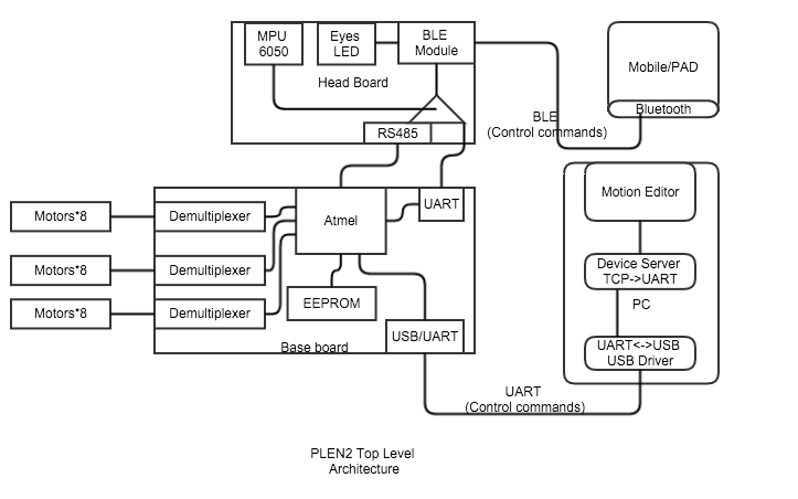
Top Level Architecture Diagram
Github structure
Robot architecture
Top Level Block Diagram
Firmware architecture
firmware.ino
AccelerationGyroSensor : AccelerationGyroSensor management
ExternalEEPROM : external EEPROM management
Interpreter : MotionController interpreter
JointController : JointController.h
pinMode(Pin::MULTIPLEXER_SELECT0(), OUTPUT);
pinMode(Pin::MULTIPLEXER_SELECT1(), OUTPUT);
pinMode(Pin::MULTIPLEXER_SELECT2(), OUTPUT);
pinMode(Pin::PWM_OUT_00_07(), OUTPUT);
pinMode(Pin::PWM_OUT_08_15(), OUTPUT);
pinMode(Pin::PWM_OUT_16_23(), OUTPUT);
namespace Pin
{
inline static const int MULTIPLEXER_SELECT0() { return 5; }
inline static const int MULTIPLEXER_SELECT1() { return 6; }
inline static const int MULTIPLEXER_SELECT2() { return 12; }
inline static const int PWM_OUT_00_07() { return 11; }
inline static const int PWM_OUT_08_15() { return 10; }
inline static const int PWM_OUT_16_23() { return 9; }
inline static const int RS485_TXD() { return 4; }
inline static const int LED_OUT() { return 13; }
inline static const int RANDOM_DEVCIE_IN() { return 6; }
}
inline static const int MULTIPLEXER_SELECT0() { return 5; }
inline static const int MULTIPLEXER_SELECT1() { return 6; }
inline static const int MULTIPLEXER_SELECT2() { return 12; }
LoadSetting
TCCR1A =
_BV(WGM11) | _BV(WGM10) | // 10bit高速PWM動作に設定
_BV(COM1A1) | _BV(COM1A0) | // 比較一致でOC1AをHIGHレベルに出力
_BV(COM1B1) | _BV(COM1B0) | // 比較一致でOC1BをHIGHレベルに出力
_BV(COM1C1) | _BV(COM1C0); // 比較一致でOC1CをHIGHレベルに出力
TCCR1B =
_BV(WGM12) | // 10bit高速PWM動作に設定
_BV(CS11) | _BV(CS10); // 前置分周64に設定
TIFR1 = _BV(OCF1A) | _BV(OCF1B) | _BV(OCF1C) | _BV(TOV1); // 割り込みフラグをクリア
/*
Execution timing is when TCNT1 overflows.
In the case of PLEN2, and multiplying the periphery 64 minutes to 16 [MHz], and because it uses a counter 10bit,
(16,000,000 / (64 * 1024)) ^ - 1 * 1,000 = 4.096 it will be interrupted every [msec].
This value of 4.096 [msec] is, to the PWM signal permissible input interval of the servo motor
It is a sufficiently small value. Therefore, once every interruption 8 times for each servo motor
Enter the PWM signal, by switching the output destination of the servomotor for each interrupt,
We have realized the control of a plurality of servo motors.
attention
Variable to be changed internally, it is safe to basically put a volatile qualifier.
By optimization of the compiler, you can prevent a confusing bug.
Since the output of the PWM signal is controlled by a double buffered by the AVR microcontroller,
The output value of the PWM signal you need to look ahead one than the referenced joint value.
Failure to this operation, since the plurality of servo motor control to an unintended behavior,
Please pay attention.
*/
ISR(TIMER1_OVF_vect)
MotionController : MotionController
Pin.h : pin setup
Purser : parser?
PurserCombinator : command combine
Soul : top level motion ( ex: face down )
System : system parameter, (ex: version, baudrate )
Reference
研究 Motion Editor 控制 Controller 的架構
Study firmware
Study how EEPROM be used
Study control server
Study motion json file
"codes": [],
"frames": [
*{
"outputs": [
{
"device": "left_shoulder_pitch",
"value": 0
},
{
"device": "left_thigh_yaw",
"value": 0
},
]
"transition_time_ms": 100
"name": "Pass to Left",
"slot": 26
Questions
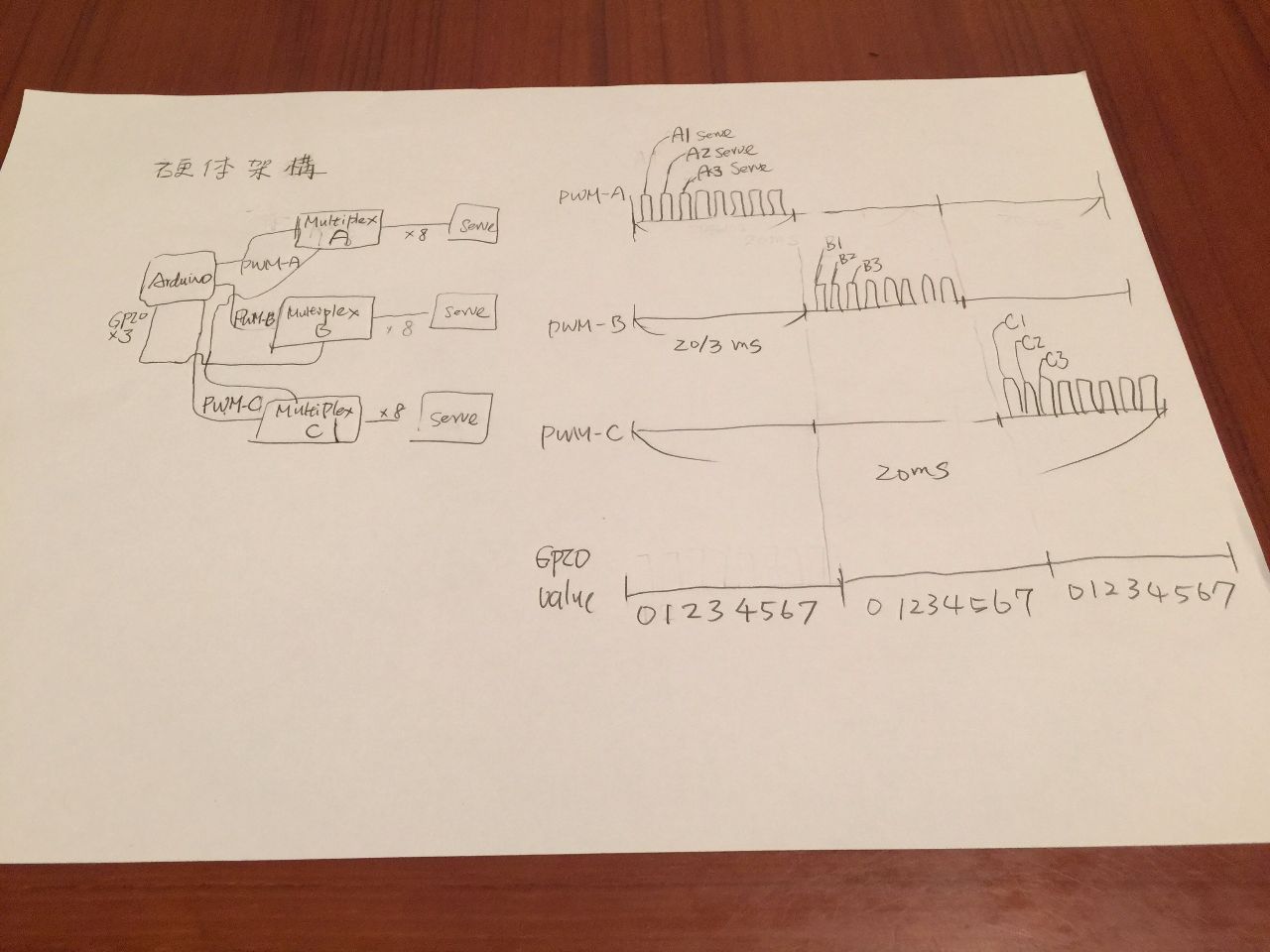
Q1 : How to use hardware PWM*3 + GPIO*3 control 24 serves?
Q2 : ASV-15 跟 SG-90 有何不同?
Q3 : 如何買?